PROTO:45
Exact-scale model railway in 1:45
by Erik Olsen
Why model railway in 1:45 scale?
I began my model railway career in N scale, 1:160, when I was 12. My father had previously built in H0 scale, and I had built a wagon and a piece of track in H0 myself. I did not have much available space, though, and as I wanted to build a layout with a couple of stations, I chose N scale.
As time went by my ambitions grew and I started building rolling stock models i N scale; I also built a few points. I wanted to make the models as prototypical as I could but I found that N scale was too small for that, and the NEM wheel standards were too coarse.
I became a member of the Danish Model Railway Club (DMJK) and started attending the club meetings, introduced by Poul Adamsen whom I knew from my membership of the Elsinore Railway Club, from the work site in Gentofte, and my subscribtion on the magazine "Signalposten". DMJK works in 0 scale (scale 1:45, track gauge 32 mm).
I was deeply fascinated by the large models and I was for many years an active member of DMJK. For different reasons I started modelling "by myself"; I was still not satisfied with the NEM wheel standards, and I was mostly interested in working with old-time models.
What is Proto:45?
The scale is still 1:45 but contrary to models built to NEM standards also wheels are built to scale.
The most important differences are that the wheel width is reduced from 4.7 mm to 3 mm, the flange height is reduced from 1.0-1.6 mm to 0.65 mm and the flange width is reduced from 1.3 mm to 0.68 mm. Correspondingly, the flangeways in points for check rails and crossings are reduced from 2.1-2.2 mm to 0.91 mm and 1.09 mm, respectively.
The Proto:45 concept means that the construction in some cases must be done to smaller tolerances than when working to NEM standards; but the differences are actually not that large. The track gauge to NEM standards is limited to 32.0-32.3 mm (tolerance 0.3 mm). Proto:45 standards use the prototype measurements divided by 45, så that the track gauge is limited to prototype 1432-1445 mm corresponding to 31.82-32.11 mm on the model (tolerance 0.29 mm).
The smaller flanges in Proto:45 means that the wheel sets will have to be sprung or equalised so that rolling stock and locomotives are not derailed. This was not so different for me as I also sprung my models built to NEM standards.
Why Proto:45?
On models of relatively heavily built modern stock where disc wheels are mostly used, the change from NEM to Proto:45 wheel standards doesn't have that large a visual impact.
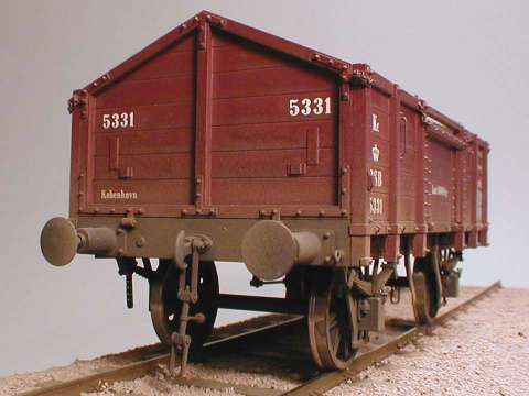
But as I mentioned earlier I am mostly interested in older rolling stock and locomotives; the models I build now is of prototypes that existed around 1900. Compared to modern stock the old-timers are more slightly constructed and spoked wheels are mostly used. On such models the proto:45 concept means that the wheels are not made larger than scale which has great visual impact on the models.
On steam locomotives built to NEM standards it is difficult to have the frames and outside cylinders placed correctly. The frames must be built narrower and the splashguards wider than prototypically and usually the cylinders have to be moved out from the frames.
If you built to Proto:45 standards this problem does not exist as the parts can be built to scale. With long-wheelbase locomotives it may be necessary to adjust the possible side movement of the wheel sets so that the locomotive will be able to run on small-radius curved track.
Proto:45 wheel standards
I have drawn the wheel profile shown in figure 1 for rolling stock wheels corresponding to a prototype wheel width of 135 mm. The wheel profile is an older prototype form used by the Danish State Railways in the 1920ies with a 1:16 thread taper. Newer prototype wheel profiles are more complex and hence more difficult to machine; it is my experience and belief that the wheel profile shown is fully adequate in model form.
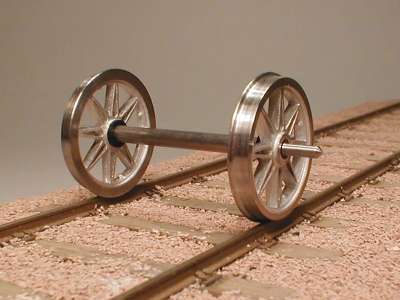
Proto:45 wheel set standards
The wheel set shown in figure 2 is intended for rolling stock with outside bearings. The journal diameter is 1.9 mm as the Teflon tube with 3 mm outside diameter and 2 mm inside diameter that I use for bearing bushings are too small to fit tightly into a 3 mm hole. That's why I drill the axle boxes 2.9 mm; after the bushings are pressed into the axle boxes, the inside bushing diameter is 1.95 mm so that a 1.9 mm journal fits nicely.
The axles have pointed ends so that there is little friction when the axles are pressed against the bottom of the journal hole when running on curved track. Originally I used 47 mm squared-off axles (an old DMJK standard) and put a 1 mm bearing ball at each end. This corresponds to a 49 mm long pointed axle.
The back-to-back distance is very important. This must always be between 30.15 mm and 30.29 mm otherwise you risk derailments in rail crossings.
I use two distance jigs from 6 mm free-cutting mild steel with the ends turned square and smooth. One is 30.15 mm long and shall be able to pass easily between the insides of the wheels. The other is 30.29 mm long and shall not be able to pass between the insides of the wheels.
The side throw of the wheels should not exceed 0.04 mm. This may be checked using a dial indicator while the wheel set is mounted in the lathe so that the journals run true. The difference between the diameters D of the wheels on a wheel set should not exceed 0.03 mm.
Springing of the wheel sets
As I've mentioned that with the small Proto:45 flanges the wheel sets need to be sprung or equalized. Normally I use working leaf springs that are made almost like the prototype springs. Figure 3 shows axle boxes and springs used for prototype Danish State Railways goods stock built from 1894 to 1916.
The W-irons are made form 0.5 mm brass or nickel silver sheet and riveted or soldered to the underframe. The axle boxes are cast from white metal and are able to slide smoothly up and down in the W-irons. The springs are made from 0.3 mm phosphor bronze sheet (etched); the ends of the uppermost leaves are formed into eyes.
The spring brackets are soldered or glued to the underframe; the spring shackles are soldered to pieces of 0.5 mm brass wire so that the assembly can move easily. Pieces of 0.5 mm brass wire are inserted through the bundles and spring bands and soldered to the upper ends of the spring bands and cut and filed flush. The lower ends of the wire are cut off 1 mm long; the wire ends are inserted into 0.6 mm holes in the axle boxes and used to guide the springs. Straps are riveted to the bottom ends of the W-irons so that the axle boxes and springs don't fall out.
Rolling stock weight
I make my rolling stock such that the axle load is at least 1.2 N (125 g) which normally is sufficient to make the leaf springs work correctly. On bogie axles the axle load may be as low as 1.0 N (100 g). This means that four-wheeled stock should weigh at least 250 g and eight-wheeled stock at least 400 g.
I feel that long coaches and wagons should be heavier that short ones. As a rule of thumb I use a weight of 100 g plus 1.0 g per mm of lenght over buffer faces. A QD-type van with a prototype lenght of 7700 mm (= 171.1 mm in 1:45 scale) thus should have a weight of approximately 271 g.
Buffers
On my models I use sprung buffers exclusively. In my opinion this is necessary in Proto:45 as a strong push on solid buffers can lead to derailment.
The buffer springs are made such that they are deflected approximately 40% when the buffer is fully extended. When the buffers are deflected approximately half of the full travel, the spring force should be 1.2-1.5 N (120-150 g). As a rule of thumb, when the wagon is stood vertically on its buffers they should be deflected approximately half the travel.
I usually make the buffer discs in scale size. This can be done because the stock I built are relatively short, and I use a minimum track curve radius of 2 m. With longer stock on small-radius track curves it may be necessary to increase the size of the buffer discs to avoid buffer locking in S-curves.
Couplings
In my opinion most automatic couplings are too clumsy and look too big on the models unless similar couplings are used on the protoype stock. On my models of older stock I only use screw couplings.
Screw couplings or 3-link couplings are of course a little difficult to use on a larger layout. More Danish clubs use the GMJS automatic coupling which is fabricated from piano wire and is one of the better 0 scale automatic couplings. I feel that the English "Alex Jackson" coupling is better still but this coupling has the drawback that it is in the way for a properly installed scale screw coupling.
Proto:45 track standards
Plain track to Proto:45 standards is not much different from track to NEM standards. The tolerance on the track gauge is a little different; the NEM standards use a gauge between 32.0 and 32.3 mm, whereas the Proto:45 standards use a track gauge between 31.82 mm and 32.11 mm. It seldom leads to problems if the gauge is a little larger than 32.11 mm (the prototype use a maximum limit of 1470 mm corrsponding to 32.67 mm in 1:45 scale).
Points to Proto:45 standards, however, differ greatly from points to NEM standards as the flangeways in Proto:45 are approximately half the width of the NEM flangeways, and the check gauge adjusted to fit the Proto:45 wheel sets.
In figure 4 is shown a cross section at the nose of a common crossing. The crossing flangeway is minimum 1.09 mm (in NEM 2.1-2.2 mm is used). The check rail is placed to the check gauge minimum 30.91 mm as the purpose of the check rail is to guide flange of the opposite wheel away from from the crossing nose.
I figure 5 is shown a cross section at the nose of an obtuse crossing as used in track crossings and slip points. The obtuse (or K) crossing is special in having two crossing noses and the check rail is often made higher than the running rails.
Obtuse crossings are always laid two oppisite each other and are more complex to construct than common crossings. Furthermore, obtuse crossings are designed such that the wheel sets are not guided through the whole lenght of the crossing gap; thus they have to be carefully constructed. On the prototype obtuse crossings are anly used with crossing angles 1:9 and larger as the distance where the wheel sets are not properly guided is too long with smaller crossing angles.