Building of switches (turnouts) in N scale
When I was a teenager and was about to start building a model railway in N scale I gave the choice of which switches (turnouts) to use much consideration. I did not have much money so the first switches I bought were cheap, and the cheapest switches then were Lima. It was around 1967.
When I had started building the model railway I soon found out that Lima switches were not that reliable. I saved a little money and bought a couple of switches from Arnold Rapido, they worked much better and looked a lot better than the Lima ones. My knowledge of prototype switches was not that large then but just the fact that the Arnold Rapido switches were more slender made me enthusiastic.
My first model railway was therefore built using Arnold Rapido switches but I kept using Peco flex track that worked well. The mixture between Arnold and Peco looked a little peculiar but it worked well. At that time, of course, all rails were code 80.
The first tests with a new method
A couple of years later I joined the Elsinore Railway Club and came in touch with the chairman of the club John Hansen who some years before was involved in plans building an N scale model of the railway station in Elsinore together with a few other members of the club. The plan had for some reason failed but I was given a large box containing track materials and unfinished switches and some home-made fixtures for constructing the switches.
It was an exciting discovery and I studied the fixtures and the unfinished switches with great interest. The switches were made after scale drawings from the Danish State Railways with crossing angle 1:9 both plain switches and slip switches. The track materials were Peco code 80 rail and strips cut from printed phenolic circuit board and wood strips for sleepers (ties) and switch timber.
There were two types of fixtures, one type made of a piece of wood with two parallel pieces of wood strip approximately 2x3mm nailed and glued down such that a rail could be fixed upside down between the wood strip pieces, and another type where the rails were held similarly by means of small brass nails without heads.
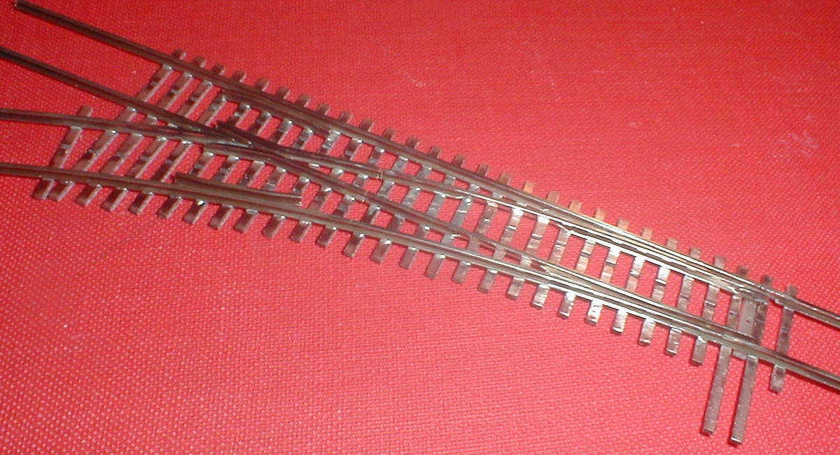
After cutting and filing the crossing vee rails were soldered together and cleaned and all rail pieces were filed and laid down in the fixture the proper way. Timber pieces from printed circuit board strips were soldered to the rail base in the proper places, and the assembled switch could be taken out of the fixture. After cleaning points rails and check (guard) rails was made and fixed and the remaining timber from wood strips were glued down.
In the mean time I had made an extension of my first layout on which I had used Peco's long switches, and soon I had torn up the old track and had started laying new track using Peco switches exclusively. For a hidden automatic meeting track (siding) I built two switches using the new method and materials. They were furnished with switch "motors" from piano wire (spring switches) and worked fairly well. They were never fully finished, though, as the remainders of the timber from wood strips were missing.
During the following years I started building other switches using the same materials and techniques, among others a scissor's crossover in curved track but that formation was never finished. In the mean time other things had happened in my life and the N scale model railway was dismantled and the materials thrown away.
Later as a member of the Danish Model Railway Club I built a large quantity of switches in 0 scale but we used more traditional techniques where the rails were fastened with rail spikes on timbers cut from 6x6mm wood strips glued onto a base of 4mm chipboard.
Later use of the method
I came to build a number of switches in H0 scale with timber from printed circuit board. There were several plain switches and a 3-way tandem switch with crossing angle 1:9 built after drawings from Danish State Railways. The materials were Roco code 100 flex track that provided the rail and timber that I cut from strips of phenolic printed circuit board and 2x3mm wood strips. The switches were used for a model of the Elsinore Railway Club project for a shed in Saunte. The real project was rather ambitious and was never constructed.
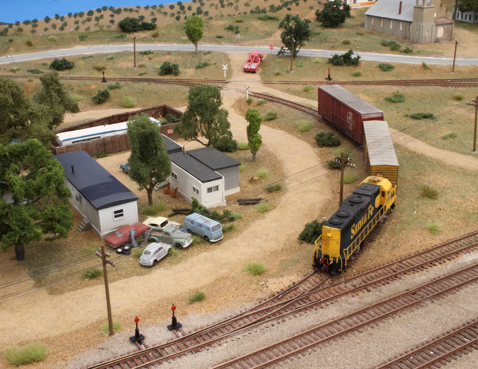
Many years later I fiddled with plans building switches for a new N scale model railway. One of my friends, Carsten Lundsten, needed two special switches for his model railway where they were to be built into a track wye in Lamy. As the space was rather limited the switches had to have the same radius as the curved track of the wye. Well, I'll make you a couple of switches that fit, I said.
Carsten's model railway can be seen at http://www.lundsten.dk/layout/index.html.
Switches for the track wye in Lamy
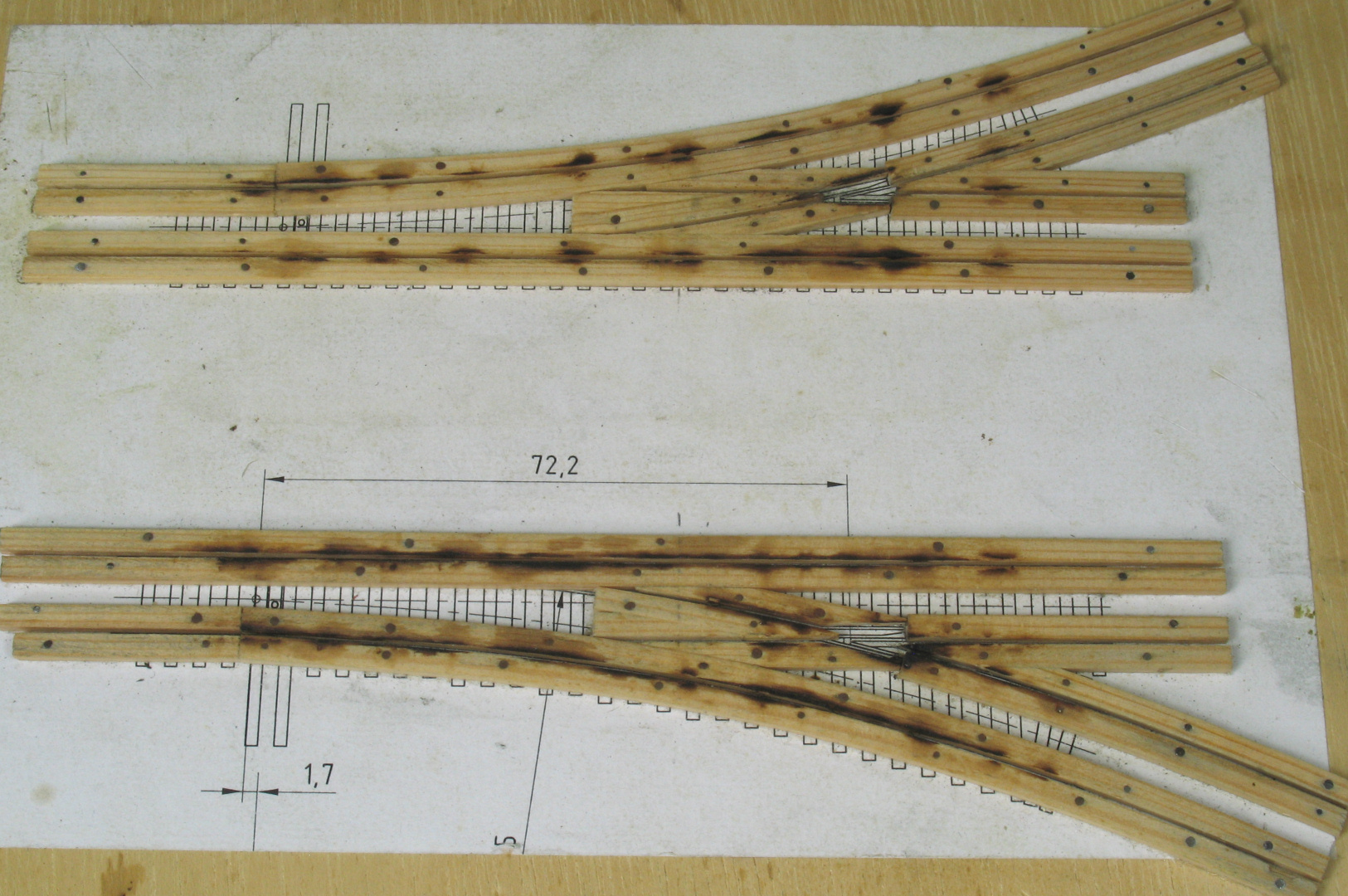
As mentioned the switches are specially fit for the place. As the track on Carsten's model railway is constructed with code 55 rail the new switches of course had to be made using the small rail. That did not cause problems as I had some code 55 rail in stock from a failed H0 scale project. We took measurements on the layout and I made some drawings that we discussed. After a few corrections I started making the fixtures for the two mirrored but otherwise identical switches.
We discussed how the point rails should be made, with hinges and root joints or as sprung point rails. Carsten preferred sprung point rails and I constructed the first switch accordingly with point rails where the base of the rail on both sides was filed away for a length of approximately 12mm to make them more flexible. This trick I had used for the switches I made in H0 scale. For the N scale switches I used timber cut from strips of double-sided fiber glass board from Clover House.
After soldering I took the switch out of the fixture and filed breaks in the copper layer of the timbers and cut the rails before the crossing for insulation. I then filled the distance between the rail ends with epoxy. I soldered on a length of wire to the crossing that later could be connected to the contacts of the Tortoise switch motor for current supply.
With sprung point rails the simple solution of soldering on a strip of printed circuit board to the point rails would not work, I had to make some sort of hinged connections. On each point rail I soldered a bent piece of 0.5mm brass wire such that one end of the wire pieces pointed downward. I cut a strip of printed circuit board where I removed the copper layers and drilled three holes in it. I placed this throw bar in the two wire ends and bent them over to retain the throw bar.
However, I had to file a bit off the brass wires where they were soldered to the point rails as it took up to much room and this made them weak. Furthermore, Carsten needed a large hole for the drive rod of the Tortoise motor so when mounting the throw bar broke. Ok, a lesson learned, so I took the switch home soldered on two new bits of wire this time from 0.4mm bronze wire which fit better and was stronger. Finally I made a new throw bar that was a little wider and had a larger middle hole.
This time the fitting to the layout went much smoother, and I constructed the second of the two switches in the same manner.
Switches built without a fixture
Some modelers prefer building switches without using a fixture for holding the rails but still use timbers from printed circuit board and solder the rails on. This may work just as well. I have found some examples on this approach on the old forum of http://www.rmweb.co.uk/ where Mike Trice has described the building of more switches to this method.
The principle of construction is that the timbers are cut from strips of printed circuit board and fastened to a drawing of the switch using double-sided adhesive tape, and the surface of the timbers are cleaning with a fiber glass brush. Then the rails are cut, filed and soldered to the timbers in a specific order. The distance is held using track gauges. Last insulation breaks are filed in the copper layer of the timbers and the rails are cut on both sides of the crossing to insulate it.
Links to Mike's articles:
Scratchbuilding Code 55 N Gauge Turnouts http://www.rmweb.co.uk/forum/viewtopic.php?f=8&t=42746
Scratching building N gauge (9mm) track http://www.rmweb.co.uk/forum/viewtopic.php?f=5&t=37908&start=25#p623846
Scratchbuilding Code 55 N Gauge Asymmetric 3 Way Turnout http://www.rmweb.co.uk/forum/viewtopic.php?f=8&t=46997
Fast Tracks switches
A canadian company, Fast Tracks, sells fixtures milled from aluminium for many different gauges, switch types, crossing angles and rail sizes. First the timbers from strips of printed circuit board are cut and put down in the fixture and on top the cut and filed rail pieces which are then soldered to the timbers. Fast Tracks also sells tools for filing crossing rails and point rails as well as a wealth of materials.
Fast Tracks web site can be found at http://www.handlaidtrack.com/. Starter sets are sold containing a fixture, tools for filing crossing rails and point rails and materials for five complete standard no. 6 switches in N scale for code 55 rail or code 40 rail for approximately 1200 DKK plus postage.
The system looks exciting and I have considered buying a starter set to see if I can manage it.
Useful links
Clover House, Post Office Box 62-W, Sebastopol, CA 95473-0062, USA, http://www.cloverhouse.com/
Fast Tracks, 47 6th Concession Rd., Brantford Ontario N3T 5L7, Canada, http://www.handlaidtrack.com/
Micro Engineering Company, 1120 Eagle Road, Fenton, MO 63026, USA, http://www.microengineering.com/The Proto:87 Stores, PO BOX 505, PISMO BEACH, CA 93448, USA, http://www.proto87.com/ (sælger også dele til skala N)